Mapping a Smoke Detector
One tiny circuit, four completely different diagrams.
Read case study →Guiding questionHow can electronic systems be incorporated into product design?
Where A3.4 gave you the vocabulary, B3.4 asks you to specify: which sensor, which output, how much current, which protocol, and what happens when the battery runs low. This is the level at which designers actually work with electronics. You are rarely the person soldering, but you are frequently the person who decided the product needed to know the temperature, and every one of those decisions has consequences in cost, power and size.
The calculations here are the most predictable marks in the topic. Ohm's law and electrical power are not difficult, and once you are comfortable rearranging them you have a reliable source of marks in Paper 2 that does not depend on how well you write. Beyond the exam, this material is unusually practical. If you have ever wanted to build something that responds to the world, the input, process and output framework plus a sensible sensor choice is most of what you need to start, and I would genuinely encourage you to try it outside of class.
Students must be able toAnalyse simple electronic products and circuits to identify the main component parts that enable them to perform a specific function.
The Input–Process–Output (IPO) model is the fundamental framework for understanding any electronic system. It breaks a complex product into three stages:
Electronics are now embedded in almost every product category: home appliances (refrigerators, washing machines, microwaves), entertainment (TVs, game consoles), communication (smartphones, computers), automotive (engine control units, GPS, advanced driver assistance), and personal wearables (smartwatches, fitness trackers). When analysing a product, the first task is to identify which components serve which stage of the IPO model.
Students must be able toDescribe how to use basic electronic measuring apparatus, including multi-meters, on voltage, current and resistance ranges, and oscilloscopes to observe waveforms.
Choosing the right instrument (and connecting it correctly) is as important as the measurement itself. Using a current meter in parallel, for example, will short-circuit the component and may destroy the meter.
Digital multimeter (DMM), the most versatile handheld instrument:
Digital storage oscilloscope (DSO): visualises voltage waveforms over time (voltage on Y-axis, time on X-axis). Indispensable for diagnosing: ringing (damped oscillations indicating impedance problems), distorted rising edges (slow component or excessive capacitance), and amplitude problems (incorrect voltage levels indicating a faulty supply). A multimeter cannot reveal any of these: it only shows a single numerical value.
Function generator: produces test signals (sine, square, triangle waves) at a chosen frequency. Frequently used alongside a DSO: the generator provides a known input, the DSO captures the circuit's response.
Clamp meter: measures current without breaking the circuit by clamping around the conductor. For AC it uses a current transformer; for DC it uses the Hall effect (detecting the magnetic field produced by the current).
Other instruments: Megohmmeter (tests insulation resistance at high voltage: a downward trend indicates insulation breakdown); Wattmeter (measures real power P = VI); LCR meter (measures inductance, capacitance and resistance using AC test signals); Logic analyser (captures multiple digital signals simultaneously to debug timing and decode communication protocols such as I²C, SPI, UART).
| Instrument | Measures | Connection | Key limitation |
|---|---|---|---|
| DMM | V, I, R | V: parallel / I: series / R: removed | Only static values: no waveform |
| DSO | Waveform over time | Parallel (high impedance probe) | Can miss very slow DC drift |
| Clamp meter | Current only | Clamp around wire (no break) | Cannot measure very low currents |
| Megger | Insulation resistance | High-voltage DC applied | Cannot test live circuits |
| LCR meter | L, C, R | Component removed from circuit | AC test signal only |
| Logic analyser | Digital signals (timing) | Probes on multiple pins | No analog voltage detail |
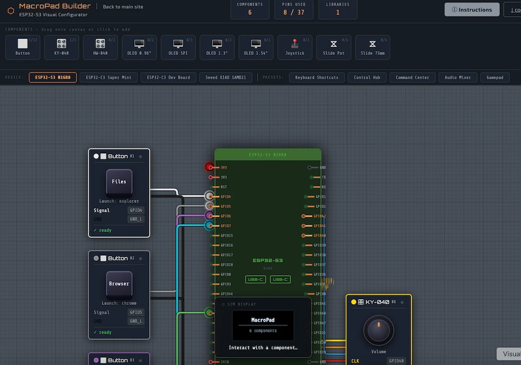
Plan the switches, wiring and components for a real macropad, then generate downloadable code to build it with an ESP32.
Students must be able toCalculate power, voltage, current and resistance in a circuit, considering V = IR and P = VI by rearranging equations and substituting values.
Ohm's law: the voltage across a component equals the current through it multiplied by its resistance.
V = I × R → I = V / R → R = V / I
Power formulas: electrical power is the rate of energy conversion. Three equivalent forms:
P = V × I = I² × R = V² / R
Use whichever form avoids an intermediate calculation step. If you know V and R but not I, use P = V²/R directly rather than calculating I first.
Single-phase vs three-phase power:
IEC 60309 industrial plug colour coding: yellow = 100–130 V, blue = 200–250 V, red = 380–480 V. Colour coding prevents incorrect connection of equipment to incompatible voltages.
Worked examples
| Given | Find | Formula | Result |
|---|---|---|---|
| V = 12 V, R = 470 Ω | I | I = V / R | I = 12 / 470 = 25.5 mA |
| V = 12 V, I = 25.5 mA | P | P = V × I | P = 12 × 0.0255 = 0.306 W |
| V = 12 V, R = 470 Ω | P (direct) | P = V² / R | P = 144 / 470 = 0.306 W |
Enter any two of V, I and R, or one of them plus P, and the rest solve automatically, with the working shown below.
Students must be able toCalculate resistance and capacitance in series and parallel in a circuit.
Resistors in series: total resistance is the sum of all resistors. Current is the same through each.
R_total = R₁ + R₂ + R₃ + …
Resistors in parallel: total resistance is always less than the smallest individual resistor. Voltage is the same across each; current splits between branches.
1 / R_total = 1/R₁ + 1/R₂ + 1/R₃ + … (for equal R: R_total = R / n)
RC circuits: a resistor (R) and capacitor (C) together create time-dependent behaviour. The capacitor charges through the resistor; the time constant τ = R × C (in seconds when R is in Ω and C is in Farads) determines how quickly voltage rises or falls.
Low-pass filter: resistor in series, capacitor in parallel with the output. Passes low-frequency (slow) signals; attenuates high-frequency (fast) signals. The capacitor charges slowly, smoothing rapid fluctuations.
High-pass filter: capacitor in series, resistor in parallel with the output. Blocks low-frequency signals (capacitor blocks DC and very slow signals); passes high-frequency signals.
Contact bounce (chatter) elimination: when a mechanical switch closes, the contacts bounce and produce multiple rapid 1s and 0s before settling. A low-pass RC filter smooths this leading edge, so the logic gate receives a clean single transition rather than a burst of false triggers.
Worked examples (resistor networks)
| Configuration | Calculation | Result |
|---|---|---|
| Series: 100 Ω + 220 Ω + 330 Ω | 100 + 220 + 330 | 650 Ω |
| Parallel: 100 Ω ∥ 100 Ω | R / n = 100 / 2 | 50 Ω |
| Parallel: 47 Ω ∥ 47 Ω | 47 / 2 | 23.5 Ω |
| Combination: 100 Ω + (50 Ω ∥ 50 Ω) | 50/2 = 25; 100 + 25 | 125 Ω |
For combination circuits, always resolve the parallel branches first, then add the series elements, just as you would apply BODMAS to arithmetic.
Students must be able toConstruct flow diagrams (using appropriate symbols) to model a programmable system that controls an electronic device.
A flow diagram (flowchart) maps the sequence of steps in an algorithm using standardised symbols. In electronics, flowcharts are used to plan and communicate how a microcontroller will respond to inputs.
Standard flowchart symbols:
Flow diagrams are useful before writing code because they separate the logic of what the system must do from the syntax of how to code it. A well-drawn flowchart can be translated directly into any programming language.
Students must be able toConstruct diagrams for simple circuits that use resistors, capacitors, switches, relays, diodes, transistors, operational amplifiers, integrated circuits, and input and output devices.
Designers use different diagram types depending on the level of detail needed and the audience for the drawing:
All four types are used in IB assessment. Block and flow diagrams are expected at a conceptual level; circuit and logic diagrams require correct use of standard symbols.
One tiny circuit, four completely different diagrams.
Read case study →Students must be able toDetermine the use of sensors to collect and input information into a digital system, including accelerometer (motion), ultrasonic (distance or proximity), photoresistor (light), voltage (moisture), hygrometer (humidity and air temperature), pressure (barometric), microphone (sound) and infrared (radiation or heat).
Sensors are the input stage of the IPO model: they convert a physical quantity into an electrical signal that a microcontroller can read. The choice of sensor must match the physical quantity being measured and the output format the processor expects (analog voltage, or digital signal).
| Sensor | Detects | Output | Typical application |
|---|---|---|---|
| Accelerometer | Motion, vibration, tilt | Analog / digital | Phone orientation, fall detection |
| Ultrasonic | Distance / proximity | Digital (pulse timing) | Parking sensors, robotics |
| Photoresistor (LDR) | Light level | Analog voltage | Automatic street lights |
| Moisture / voltage | Soil or liquid conductivity | Analog | Plant watering systems |
| Hygrometer | Humidity and air temperature | Analog / digital | HVAC, weather stations |
| Barometric pressure | Atmospheric pressure | Analog / digital | Weather apps, altimeters |
| Microphone | Sound | Analog (AC) | Voice control, noise monitoring |
| Infrared / PIR | Heat, radiation, motion | Digital | Intruder detection, touchless switches |
| Hall effect | Magnetic field strength | Analog / digital | Speed sensors, position sensing |
| Gas sensor | Chemical concentration | Analog | CO detectors, air quality monitors |
Students must be able toCreate simple circuits that use microcontrollers as a programmable integrated circuit (PIC) with appropriate software to carry out a predetermined task.
An embedded system is a dedicated computer system designed to perform a specific function within a larger product. Unlike a general-purpose computer, it runs one fixed program stored in its memory.
The heart of the process stage is a microcontroller (MCU), also referred to as a programmable integrated circuit (PIC). A microcontroller integrates on a single chip:
Educational platforms such as Arduino (AVR/ARM microcontrollers) and Raspberry Pi (single-board computer) make it accessible to prototype embedded systems. In industry, dedicated MCUs (e.g., STM32, PIC, ATmega) are chosen for their size, power consumption and cost.
Students must be able toDescribe digital systems in terms of the binary number system, Boolean algebra, logic gates such as AND, OR and NOT, combinational logic circuits and sequential logic circuits, and be able to construct truth tables for a digital circuit.
All digital systems represent data using binary: a base-2 number system using only 0 and 1 (off and on). Multiple binary digits (bits) represent larger values: 8 bits = 1 byte, capable of representing 256 values (0–255).
Boolean algebra defines how binary values are combined using logical operations. Three fundamental gates:
A truth table lists every possible combination of inputs and the corresponding output. For n inputs there are 2ⁿ rows.
Combinational logic: the output depends only on the current inputs. No memory: the same input always produces the same output. Examples: AND, OR, NOT, NAND, NOR, XOR gates.
Sequential logic: the output depends on current inputs AND previous states. Uses memory elements (flip-flops). Examples: counters, registers, state machines: the basis of most microcontrollers.
Truth tables (AND, OR, NOT)
| A | B | A AND B | A OR B | NOT A |
|---|---|---|---|---|
| 0 | 0 | 0 | 0 | 1 |
| 0 | 1 | 0 | 1 | 1 |
| 1 | 0 | 0 | 1 | 0 |
| 1 | 1 | 1 | 1 | 0 |
Students must be able toDetermine appropriate output devices to communicate information or physically control an environment, including motors (including servos and pumps), LCD display (communication and light), buzzer (sound) and relay (mechanical).
Output devices are the third stage of the IPO model: they convert the processed electrical signal into a physical action or visible/audible communication.
| Output device | Function | Notes |
|---|---|---|
| DC motor | Continuous rotary motion | Speed controlled by PWM; direction by H-bridge circuit |
| Servo motor | Precise angular positioning (0–180°) | Position set by PWM pulse width; used in robotic arms, steering |
| Pump | Fluid movement | Essentially a motor with an impeller; used in irrigation, aquariums |
| LCD display | Text and numeric information | Communicates data to the user; requires no moving parts |
| Piezo buzzer | Audible alert or tone | Simple alarm; frequency can be varied to produce different tones |
| Relay | Switches a separate high-power circuit using a low-power control signal | Electrically isolates the control circuit from the load circuit; used to switch mains voltage from a 5V microcontroller output |
When selecting an output device, consider three things: the type of action needed (motion, information, sound), the voltage and current required by the device, and whether the microcontroller can drive it directly or needs an amplifying component (transistor, relay, or motor driver IC).
A microcontroller's digital output pin can only be fully on or fully off; it has no way to produce an intermediate voltage directly. PWM works around this by switching the pin on and off very rapidly and varying the proportion of time it spends on, called the duty cycle. A device that responds to average power rather than to the instant-by-instant signal, such as a motor or an LED, behaves as if it were receiving a steady intermediate voltage.
A 0% duty cycle is equivalent to fully off, 100% is fully on, and 50% behaves roughly like half power. This is exactly how DC motor speed and servo position are controlled in the output device table above: a DC motor's average rotational speed scales with duty cycle, while a servo reads the pulse width of each cycle (not the average) to determine the angle it should hold.
Students must be able toCompare the protocol embedded systems used to communicate with other systems (Wi-Fi vs Bluetooth vs 5G).
Embedded systems often need to communicate with other devices or networks. The choice of wireless protocol depends on range, speed, power consumption and the infrastructure available.
Bluetooth: designed for low-power, short-range device-to-device communication. Operates at 2.4 GHz using frequency hopping to reduce interference. Typical range: ~10 m. Uses a layered protocol stack: the Controller layer (Radio, Link Manager, Voice CODEC) communicates with the Host layer (GAP, GATT, ATT, SMP, RFCOMM) via the HCI interface. GAP (Generic Access Profile) governs device discovery and connection setup. Used in: wireless earbuds, keyboards, fitness trackers, medical devices.
Wi-Fi: high-speed, medium-range local area network access. Connects devices to a router (and thus the internet). Higher power consumption than Bluetooth. Range: ~50 m indoors. Used in: laptops, smart home devices, IP cameras.
5G: fifth-generation cellular technology. Offers ultra-high data speeds, ultra-low latency, and the ability to connect massive numbers of devices simultaneously. Does not require a local router: connects directly to the cellular network. Used in: autonomous vehicles, smart cities, large-scale IoT deployments.
Case study (Australia's 3G shutdown, October 2024): Many 4G phones were designed to fall back to 3G for voice calls because 4G voice required a separate technology called VoLTE (Voice over LTE). When Australia's ACMA shut down the 3G network, non-VoLTE phones lost all voice capability, including emergency calls. Even medical alarms and personal emergency response devices stopped working. The lesson for embedded systems designers: never assume that legacy infrastructure will remain available. Design for forward compatibility and include graceful upgrade paths.
| Protocol | Range | Speed | Power | Infrastructure needed | Best for |
|---|---|---|---|---|---|
| Bluetooth | ~10 m | Moderate | Very low | None (peer-to-peer) | Wearables, peripherals, medical sensors |
| Wi-Fi | ~50 m | High | Moderate | Router / access point | Smart home, streaming, internet access |
| 5G | Kilometres | Ultra-high | Higher | Cellular network | Autonomous vehicles, smart cities, IoT at scale |
Ten questions sampling across the eleven learning objectives. Select one answer per question, then click "Check all answers" to see your score and the explanations.
A bicycle rear light runs from a single lithium cell and must stay visible for a long ride. The designer must set the current through the LED with a series resistor.
Table 1: Rear light circuit
| Quantity | Value |
|---|---|
| Supply voltage | 3.7 V |
| LED forward voltage | 2.1 V |
| Series resistor | 80 Ω |
| Cell capacity | 500 mAh |
| LED maximum continuous current | 30 mA |
(a) State the purpose of the series resistor in this circuit, see Table 1. [1]
(b) Apply Ohm's law to determine the current through the LED, see Table 1. [2]
(c) Explain why the light flashes rather than shining continuously, see Table 1. [3]
(a) To limit the current through the LED to a safe value.
(b) The resistor drops 3.7 − 2.1 = 1.6 V. Current = V ÷ R = 1.6 ÷ 80 = 0.02 A, so 20 mA. That is below the LED's 30 mA maximum, so the resistor value is safe.
(c) At 20 mA a 500 mAh cell would last about 25 hours of continuous running, and a light that has to be recharged after a few night rides will be found flat when it is needed. Flashing at a low duty cycle, for example on for a tenth of the time, cuts the mean current to about 2 mA and extends the life to hundreds of hours, which is what turns the light into something a rider can leave on the bike. The reason this works without losing the light's function is that visibility does not depend on the light being on continuously. A driver has to notice the light, and a changing source draws the eye far more effectively than a constant one of the same brightness, so a flashing light is actually more conspicuous while using a fraction of the energy. Flashing also allows the LED to be driven harder during each pulse than its continuous rating permits, because it has time to cool between pulses, so the peak brightness can exceed what 30 mA would allow continuously.
(a) • To limit the current through the LED ✓
• To protect the LED from excessive current ✓
• To drop the surplus supply voltage ✓
Award [1] for the correct purpose up to [1 max].
(b) Voltage in a circuit is calculated by a combination of current and resistance.
• Voltage across the resistor = 3.7 − 2.1 = 1.6 V ✓
• I = V ÷ R = 1.6 ÷ 80 = 0.02 A = 20 mA ✓
• 20 mA is below the 30 mA maximum, so the value is safe ✓
Award [1] for the correct voltage across the resistor and [1] for the correct current, up to [2 max]. Do not credit 3.7 ÷ 80, which ignores the LED forward voltage.
(c) Electronic systems utilise output devices to perform a function in response to an initial stimulus.
• At 20 mA a 500 mAh cell lasts about 25 hours of continuous running ✓
• A light needing recharging after a few night rides will be found flat when needed ✓
• Flashing at a low duty cycle cuts the mean current ✓
• On for a tenth of the time gives about 2 mA mean, extending life to hundreds of hours ✓
• That makes the light something a rider can leave on the bike ✓
• Visibility does not require the light to be on continuously ✓
• A changing source draws the eye more effectively than a constant one of equal brightness ✓
• A flashing light is more conspicuous while using less energy ✓
• The LED can be driven above its continuous rating during each pulse ✓
• It cools between pulses, so peak brightness can exceed what 30 mA allows continuously ✓
Award [1] for each relevant reason / cause explaining why the light flashes up to [3 max]. Credit both the energy argument and the conspicuity argument.
A refrigerator sounds an alarm if the door is left open. It must sound only when the door has been open for more than 45 seconds, and must not sound while the door is being opened and closed normally.
A reed switch on the door frame gives a logic HIGH when the door is open.
Table 2: Alarm system elements
| Element | Component | Signal |
|---|---|---|
| Input | Reed switch and magnet | Digital, HIGH when open |
| Input | Thermistor in cabinet | Analogue |
| Process | Timer and logic gate | — |
| Output | Piezo sounder | 3 V, 15 mA |
(a) State the logic gate needed to sound the alarm only when the door is open and the timer has elapsed, see Table 2. [1]
(b) Describe why a timer is required between the reed switch and the sounder, see Table 2. [2]
(c) Justify driving the piezo sounder directly from a microcontroller pin rather than through a relay, see Table 2. [3]
(a) An AND gate.
(b) Without a timer the alarm would sound the instant the door opened, which is every time anyone takes anything out, so a signal meant to indicate a fault would accompany normal use and be ignored. The timer distinguishes the two states by duration: opening for a few seconds is normal, and remaining open past 45 seconds is a fault, and duration is the only thing separating them since the switch reads identically in both cases.
(c) A relay exists to bridge a gap between what a pin can supply and what a load needs, and here there is no gap. The sounder draws 15 mA at 3 V, which a microcontroller pin supplies directly, so a relay would be a component added to solve a problem the circuit does not have. Adding it would make the product worse in several ways: the relay itself draws more current than the sounder it switches, which matters in a device that runs continuously for years, and it is an electromechanical part with contacts that wear, so it would become the least reliable component in an otherwise solid-state circuit. It also costs more and takes board space in an appliance made in high volume. The isolation a relay provides is unnecessary because there is no mains voltage on the output side, and driving the piezo directly has a positive advantage as well, since the pin can be switched rapidly to generate the tone rather than needing a separate oscillator.
(a) Digital systems use logic to compare input data.
• AND ✓
Award [1] for the correct logic gate up to [1 max].
(b) Digital systems at the second stage of the input-process-output model use control circuits to monitor and control.
• Without a timer the alarm sounds the instant the door opens ✓
• That is every time anyone takes anything out ✓
• A fault signal accompanying normal use would be ignored by the user ✓
• The timer distinguishes the two states by duration ✓
• Opening for a few seconds is normal; staying open past 45 s is a fault ✓
• The switch reads identically in both cases, so duration is the only distinguishing information ✓
• It also prevents nuisance alarms from switch bounce as the door closes ✓
Award [1] for each detail, leading to an account of why a timer is required, up to [2 max].
(c) Electronic systems utilise output devices to perform a function, and interface components are selected to match the load.
• A relay bridges a gap between pin capability and load demand ✓
• The sounder draws 15 mA at 3 V, which a pin supplies directly ✓
• There is no gap, so a relay solves a problem the circuit does not have ✓
• A relay coil draws more current than the sounder it switches ✓
• That matters in an appliance running continuously for years ✓
• A relay is electromechanical with contacts that wear ✓
• It would be the least reliable component in an otherwise solid-state circuit ✓
• It costs more and takes board space in a high volume product ✓
• Isolation is unnecessary, since there is no mains voltage on the output side ✓
• A directly driven pin can be switched rapidly to generate the tone ✓
• No separate oscillator is then required ✓
Award [1] for each valid reason / piece of evidence justifying direct drive up to [3 max]. Award a maximum of [2] where the response does not compare the load with the pin's capability.
A beekeeper wants to monitor hives remotely. Opening a hive to inspect it chills the colony and disturbs the bees, so a monitor that reports on the colony without opening it would reduce the number of inspections needed.
Hives stand in fields with no mains power and no reliable phone signal.
(a) Identify two input devices that would report usefully on a colony without the hive being opened. [2]
Table 3: Monitor specification
| Element | Component | Detail |
|---|---|---|
| Input | Load cell under the hive | Analogue, 0–200 kg |
| Input | Temperature and humidity sensor | Digital, in the brood box |
| Process | Microcontroller | Sleeps between readings |
| Output | Radio transmitter | Sends once per hour |
| Power | Solar panel and cell | 2 W panel, 6600 mAh cell |
(b) Outline what a change in the load cell reading tells the beekeeper, see Table 3. [2]
The microcontroller spends most of each hour asleep, drawing a few microamps, waking briefly to take a reading and transmit.
(c) Describe why the microcontroller sleeps between readings, see Table 3. [2]
The designer must choose how the monitor sends its data. Wi-Fi needs a nearby access point. A mobile connection needs signal and a monthly subscription per hive. A long-range low-power radio can reach several kilometres to a single receiver at the beekeeper's house, but sends only small amounts of data.
(d) Explain which communication method should be selected, see Table 3. [4]
(a) A load cell under the hive to weigh it, and a temperature sensor in the brood box.
(b) A steady rise through the day means the bees are bringing in nectar, so the colony is foraging and the flow is on, and a rise fast enough to fill the box tells the beekeeper to add another before the bees run out of room. A fall means the colony is consuming stores rather than gathering, and a sudden large drop means the hive has swarmed or been stolen or knocked over.
(c) The monitor runs from a 2 W panel in a field, and a microcontroller drawing its full running current continuously would flatten a 6600 mAh cell in a few days and could not be recharged through winter or a run of dull weather. Sleeping at a few microamps means the device draws almost nothing for the 59 minutes an hour when it has nothing to do, so the average current is set by the brief wake period, and the cell lasts through periods when the panel generates almost nothing.
(d) The long-range low-power radio is the correct selection, because the constraints in this application are exactly the ones it is designed for.
Wi-Fi fails first. It needs an access point within a few tens of metres, and the hives are in fields, so there is nothing to connect to. Even if a link could be arranged, Wi-Fi is power hungry, and a device on a 2 W panel cannot afford a radio that draws heavily every time it associates with a network.
A mobile connection is technically workable but poorly matched. The case study says signal is unreliable, and a monitor that reports only when the network happens to be available is worth little, since the events the beekeeper cares about are exactly the ones needing prompt action. The subscription per hive is the bigger objection, because a beekeeper with twenty hives pays twenty subscriptions forever, and the monitor's value is saving inspections rather than generating income.
The low-power radio matches every constraint. Several kilometres covers hives in fields around a beekeeper's house, one receiver serves every hive so there is no cost per unit, and there is no subscription at all. Its limitation, that it sends only small amounts of data, costs nothing here: the payload is a weight, a temperature and a humidity figure once an hour, which is a few bytes. Low power is not merely acceptable but necessary, since the transmitter is the largest single consumer in the device and cutting its energy is what makes the solar budget work.
The design should therefore use the low-power radio, with the receiver at the house handling the internet connection. That puts the mains-powered part where mains power exists and keeps every hive-mounted unit cheap, subscription-free and within its energy budget.
(a) Digital systems at the first stage of the input-process-output model use inputs to sense changes in their environment.
• Load cell to weigh the hive ✓
• Temperature sensor in the brood box ✓
• Humidity sensor ✓
• Microphone to detect colony sound ✓
• Accelerometer to detect the hive being knocked or moved ✓
• Infrared beam counting bees at the entrance ✓
Award [1] for each relevant input device up to [2 max]. The device must work without the hive being opened.
(b) Electronic systems utilise input devices to identify a change in an environment that requires a response.
• A steady rise through the day means nectar is being brought in ✓
• The colony is foraging and the nectar flow is on ✓
• A fast rise warns that another box is needed before the bees run out of room ✓
• A fall means the colony is consuming stores rather than gathering ✓
• A sustained fall in winter tracks stores and warns of starvation ✓
• A sudden large drop indicates a swarm, theft, or the hive being knocked over ✓
• The trend matters more than the absolute value ✓
Award [1] for each relevant brief point on what a weight change indicates up to [2 max]. Credit both rising and falling interpretations.
(c) Electronic systems are designed so that they may be used responsibly, including managing their energy consumption.
• The monitor runs from a 2 W panel in a field with no mains ✓
• Continuous running would flatten a 6600 mAh cell in a few days ✓
• It could not be recharged through winter or a run of dull weather ✓
• Sleeping at a few microamps draws almost nothing for 59 minutes of each hour ✓
• Average current is set by the brief wake period ✓
• The cell then lasts through periods when the panel generates little ✓
• Hourly readings are frequent enough for the events being monitored ✓
• It also allows a smaller cell and panel, reducing cost per hive ✓
Award [1] for each detail, leading to an account of why the microcontroller sleeps, up to [2 max].
(d) Digital systems at the third stage of the input-process-output model use the output to communicate to or control their environment.
Rejecting Wi-Fi:
• Needs an access point within a few tens of metres ✓
• The hives are in fields, so there is nothing to connect to ✓
• Wi-Fi draws heavily on every association, which the 2 W panel cannot support ✓
Rejecting mobile:
• Signal is stated to be unreliable at the hive sites ✓
• A monitor reporting only when the network allows is worth little ✓
• The events the beekeeper cares about are the ones needing prompt action ✓
• A subscription per hive multiplies across twenty hives, forever ✓
• The monitor saves inspections rather than generating income, so recurring cost is hard to justify ✓
Selecting the low-power radio:
• Several kilometres covers hives in fields around the beekeeper's house ✓
• One receiver serves every hive, so there is no cost per unit ✓
• No subscription at all ✓
• The small payload limit costs nothing, since a reading is a few bytes ✓
• Low power is necessary, not merely acceptable ✓
• The transmitter is the largest single consumer, so its energy decides the solar budget ✓
System design:
• The receiver at the house handles the internet connection ✓
• That puts the mains-powered part where mains power exists ✓
• Every hive-mounted unit stays cheap and within its energy budget ✓
Award [1] for each relevant detail / reason / cause supporting the selection up to [4 max]. Credit a justified selection of any method. Award a maximum of [3] where the response does not weigh at least two options against the constraints in Table 3.
Linking Questions
A household photoelectric smoke detector is small enough to hold in one hand, but a full technical description of it needs several different diagrams, exactly the four types described above, because no single diagram answers every question a designer, technician or programmer might have about it.
A block diagram shows the shape of the problem at a glance: a light source and a light sensor sit inside a dark chamber, watching for smoke particles to scatter light onto the sensor; a comparator IC checks that reading against a threshold; a piezo siren sounds if it's exceeded. A circuit diagram would replace those labelled boxes with the actual IR LED, photodiode, op-amp comparator and their component values, everything a technician would need to build or repair the board. A logic diagram would isolate just the alarm-triggering decision as gate logic: sound the alarm if smoke is detected AND the hush button isn't currently held, OR if the test button is pressed, the AND/OR/NOT arrangement a designer would need if that decision were built from discrete logic gates rather than written as code. A flow diagram, the kind introduced in 3.4.5, would instead describe the microcontroller's behaviour: read sensor, is the light level above threshold, if yes sound the alarm and flash the LED, if no wait and read again. Four completely different pictures of the same 2-centimetre circuit board, each one answering a different question about it.